
Following text describes discrete PID regulator with sound card as an input/output interface
to the process. This idea I saw on some forum seemed pretty interesting to me because there is no need for complex
analog/digital input/output interface. Both feedback and output signals can be processed/generated directly with
sound card (software).
I was curious how will this idea work so I started writting simple input/output functions and the regulator.
Everything seemed to work just fine so I decided to make it a bit more complex. I recycled few of my older university projects
aimed to online process model identification and regulator self-tunning and I implemented these algoritms into my new program.
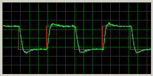
|
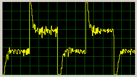
|
|
|
- Input interface
- Output interface
- Sound blaster timming
- Program structure
- Some theory
- The program and its usage
- Results
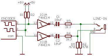
For my experiment I choosed small DC motor. In this case the best option for feedback is rotary encoder. Quadrature encoder can be connected directly to the LINE-IN via some capacities and votlage dividers:
|
In my case I got 70% of fullscale signal for maximal input sensitivity which is optimal.
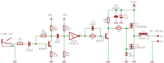
The simplest control method for DC motors is PWM modulation. It can be generated directly on LINE-OUT output. Following circuits amplifies the signals and drives the motor:
|
Used solution is not optimal but I had no other components at the time. :-)
Principle of operation is simple: T1 amplifies the signal from sound card LINE-OUT output, derivator C2, R5||R6 generates on/off pulses for schmidt FF.
Power stage can be used for voltages up to 15V (MOSFET gates won't survive more than some 18V). Zener diode just protects the gate from peaks induced via drain-gate capacity.
Output choke is used for current smoothing. It's not necessary but it is better to use it at least for lower PWM frequencies.
A small problem of this solution is that it can stack in any state if there are no pulses from sound blaster so
the PWM waveform is limited to change its state at least once during period - the duty cycle is never 0 or full 100%.
In my case the interface worked fine with frequencies 100Hz up to 1kHz which is enough for small DC motors.
This interface can be used only for one direction motor control. For bidirectional control it's necessary to build full bridge. Then 50%
duty cycle will be equal to zero current through motor.
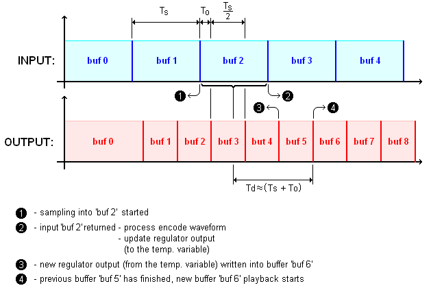
Quite important problem was to setup timing. It is obvious that there is certain delay from encoder sampling start (1) to output waveform change (4). Graphical illustration of the problem:
|
First delay is caused by the fact that the input (feedback) is calculated as mean for whole sampling period (1) to (2),
i.e. average delay Ts/2. Next problem is that the output has to be at least double buffered so there might be new delay Ts. To reduce this interval
output buffers have half size than input ones so the delay from (3) where the buffer is filled with new data to (4) where starts its playback is only Ts/2.
Last delay that appears is necessary input-output time offset. This delay is essential because feedback processing and regulator output calculation takes some time.
Minimum reliable delay from (2) where feedback is available to new output request (3) is some 10ms.
Total delay added to process by the sound blaster interface is (Ts + To). That is some 80ms at least.
For shorter buffers I had problems with output buffer underflows.
The delay can be reduced by writting into output buffers while there are still in use but I don't think this is very clean solution.
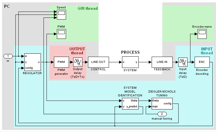
Block diagram of whole program:
|
The program is splitted into (at least) three threads to ensure correct timing.
Main thread is Borland VCL GUI that controls all other modules of the program.
Input buffers with feedback waveform from sound blaster are processed in separate thread and this thread also does all the calculations
because those are always dependent on new input data.
Time critical output is also generated by its own thread, in this case with higher priority. This ensures that
it will work properly even on slow single core PC's (successfully tested on P3 1GHz). Any time system requests to fill new output buffer the thread is
resumed and since it has higher priority it should be processed preferably.
Following text describes some theory and algorithms used in this program.
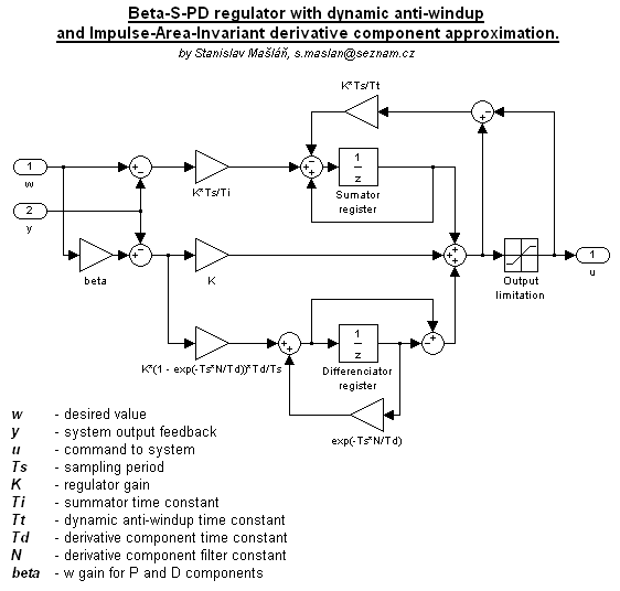
At first I wanted to try just some simple discrete PID regulator but it did work fine so I decided to implement so called beta-I-PD topology with dynamic anti-windup because this topology gives user more options to modify closed loop response shape than ordinary PID. Block diagram of this topology:
|
Derivative component is of course filtered, unfiltered version usually just does more harm (especially for fast sampling).
It amplifies the noise and generates nasty spikes that are very unhealthy for mechanical parts of the process. Filtered derivative component decreases
the amplitude and stretches the pulse to longer time period so it is less harmfull to process and it also doesn't amplifies the noise so much.
The discrete approximation I used is called Impulse-Area-Invariant. This is relatively new method designed at
Brno Technical University (Faculty of Electrical Engineering and Communication) and as far as I remember it's only true equivalent
for continuous version. It is designed to have exactly the same pulse energy as continuous version independently to smapling period.
This allows to use the same regulator tuning methods as for continuous PID.
Anti-windup algorithm is dynamic with time constant Tt. It is one more parameter to set but
it's also one more parameter that allows user to modify shape of the closed loop response.
Reason for the beta parameter is following: The main goal of the regulator is of course to effectively regulate
system error acting at its input or output (that is why closed loop is used instead of open loop).
The primary requirement is to have reasonable response to error change at the input
or output of the system but it is also often required to have certain shape of the response to desired value w change. These two requirements are almost
in opposite because if the regulator has fast response to error step acting for example at process input then it has also high overshoot or oscillations in
response to control input step. This is the case where beta-I-PD topology can be used as an simpler alternative to full topologies with two degrees of freedom.
The beta parameter changes sensitivity of P and D components
to control input w while I component stays the same as for PID to ensure zero regulation error (that's why it's called I-PD).
For beta=1 the topology acts as ordinary PID but when decreasing the coefficient value the control step response
overshoot decreases while response to error change stays unchanged. This way both requirements can be fulfilled.
Some additional informations about Impulse-Area-Invariant method:
PIVOŇKA, Petr., SCHMIDT, Michal. Comparative Analysis of Discrete Derivative Implementations
in PID Controllers. 2007. Brno University Of Technology, Department of Control and Instrumentation,
Kolejní 2906/4, CZECH REPUBLIC.
After debugging the input, output and regulator functions I decided to add online process model identification (realtime, in-system) and regulator auto-tuning.
There are lots of different methods for this but I decided to recycle one of my university projets that uses single neuron ARX model with
Steepest Descent minimising algorithm. It might sound a bit complicated but it's actually one of the simplest methods.
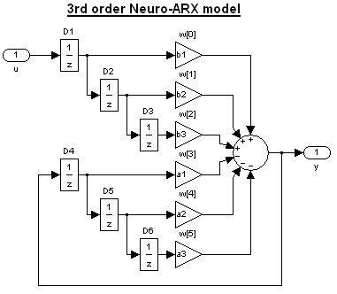
Z-transfer function Fs(z) to find is defined as:

where coefficients a1,2,3 and b1,2,3 are model parameters to identify. Third order system might be a bit much for DC motor but on the other hand at least one numerator coefficient (b1) will be "consumed" by the transfer delay and CPU power requirements are not an issue in these days. Neural "network" realization of Fs(z) system:
|
Input weights vector w contains model parameters in this order:

The SD algorithm requires only two things: Matrix X with n patterns to learn and vector t with corresponding observations. Matrix X contains delayed process inputs u and outputs y in following order:

where u-k and y-k are input/output samples delayed by k periods. Every row is one pattern to learn. Vector of the observations t contains delayed output samples:

The main SD algorithm with so called optimal step ε is defined as follows:
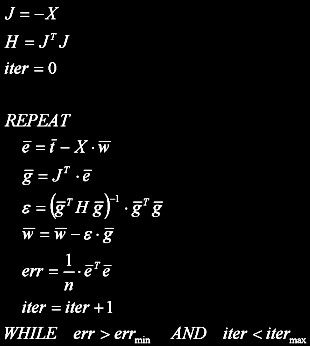
Entire algorithm uses only basic matrix operations. Inversion used for ε calculation is only scalar so it's not necessary to implement. matrix inversion. The learning process is finished once the model error decreases under defined limit or if maximum number of itterations is made. Single step prediction of the model output:

Since optimal step ε is used the algorithm is quite simple to setup. It's only necessary to set
reasonable patterns count, i.e. how far to the past it sees. Minimum count is limited to some 20 because of stability of identified parameters and
maximum count to some 1000 samples because of CPU requirements.
Next thing to set is model error limit and itterations count limit. Desired error should be set to value that
can be reached after some reasonable time because otherwise the SD algorithm will always run full itterrations count and it will learn even
the noise in the patterns (overfitting).
Some informations about the SD method:
MEZA, Juan. Steepest Descent. Lawrence Berkeley National Laboratory
Berkeley, California 94720.
Probably the simplest method is good old Ziegler-Nichols. For this method it's necessary to calculate critical closed loop gain Kk and oscillations period Tk. From these two parameters PID setup can be calculated:
K = 0.6*KkTi = 0.5*Tk
Td = 0.125*Tk
Alternative version for suppressed overshoot:
K = 0.3*KkTi = 1.0*Tk
Td = 0.125*Tk
Calculation of critical parameters for 2nd order system is very simple, for 3rd order it's a bit more complex. Calculation is based on characteristic polynomial of closed loop with P regulator:

where Fw is transfer function of closed loop, Fs system transfer function, Fr regulator transfer function and Kk is critical gain to find.
Characteristic polynomial contains three poles. System can be asymptotically stable and oscillating at the same time in two cases.
In first case complex pair of poles lies at unit circle and the remaining pole is stable (inside the circle):

Two solutions can be found from following equation:

One of the solutions might be valid if:

If none of those is valid then the second case is possible: one real pole at unit circle (z = -1) and the remaining poles stable:

Period of oscillations Tk is given by sampling rate only in this case.
The program was written in BDS2006 Turbo C++ and tested in windoze XP. It was debugged on Intel Core i5 (4 cores) but it did work even on my old P3 1GHz. The program should work in windoze 7 as well (I hope that M$ didn't modified sound APIs). It is not well optimized, I'm not using any specialized libraries for matrix operations and especially the graphs are quite uneffective because these are partially drawn via TCanvas class which is known to be very slow.
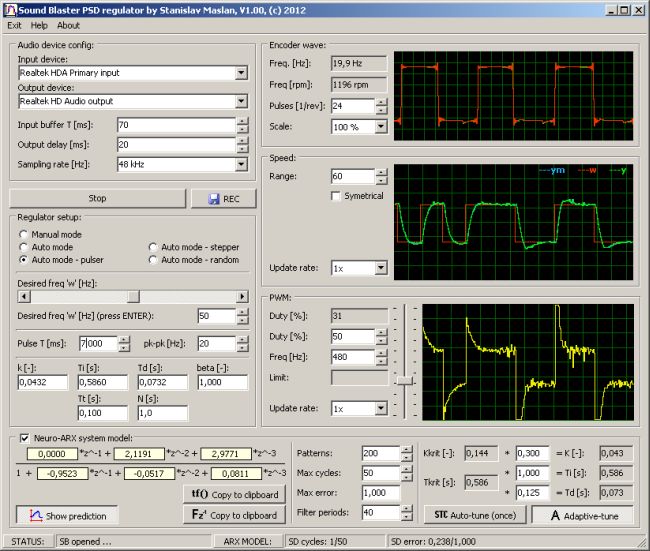
|
The program is composed from several units I made earlier so it's a bit inconsistent but there are
lot of comments so I hope is no problem to understand its function.
Everything except main GUI module is written in C/C++ using only standard libraries and WinApi for sound blaster
(windows.h, mmsystem.h).
Program and source code V1.00, 10.10.2012 download: SB_regulator.zip (980kB).
The code can be used in any project but it was designed only for learning purposes so author is not responsible for its proper function!
At first it is necessary to choose LINE-IN input and set reasonable sensitivity in sound card drivers.
Sensitivity should be set to some 60-80% fullscale signal according to input waveform scope (in my case with used interface it was full sensitivity).
Next thing is to choose input and output device. Important is that both devices must be
physically part of one sound card otherwise the sample rates will be different and timing according to
paragraph 3 won't work!
Regulator sampling period should be set according to the process behaviour.
Shortest possible period was in my case 70ms (output buffer than have only 35ms).
For shorter periods there might be output buffer underflows indicated by discontinuous sound.
Next possible setup is output interval delay which should be set somewhere between 10ms and Ts/2. Safe value that should
work is 20ms.
Sampling rate should be set at least to 44.1kHz. Faster sampling rate decreases PWM waveform noise and increases encoder resolution.
If it's possible it should be set to 96 or even 192kHz (not all sound cards supports it).
In encoder section it's possible to set impulse count per encoder revolution. Encoder is decoded always as quadrature so if single channel is used (one direction sensor) both LINE-IN inputs should be feed with the same signal! If bidirectional control is required it's necessary to enable "Bidirect" checkbox in "Speed" section. PWM duty cycle for zero motor current is then 50%.
Here you can manually control PWM duty cycle if manual mode is enabled and you can specify desired PWM frequency. Input interface was designed for range from 100Hz to 1kHz. Lower frequency is not very healthy for DC motor and higher has lower resolution which results in higher output noise.
Here it's possible to choose operation mode. Manual allows to control PWM duty cycle directly by trackbar next to the PWM graph. In auto mode the regulator
is enabled and if one of additional modes is choosen the program automatically generates desired value w waveform to ease the identification and regulator tunig.
In auto mode it is possible to manually enter regulator parameters according to algorithm description
5.1. Only parameter that can be kind of problematic is dynamic anti-windup time constant Tt.
If it's too high the function does nothing. If it's
too low the loop might became unstable so this value should be slowly decreased until it starts affecting regulator response.
Of course it affects only if command (PWM duty cycle) reaches the limitations.
In this section current model transfer function is displayed. It can be exported in two formats compatible
with Matlab and Octave simulation software. Parameters of Steepest Descent algorithm
(5.2)
can be modified here. There is also simple averaging filter. If it's not required it can be set to single period.
Last settings in this section are Ziegler-Nichols multipliers
(5.3)
that can be set to any values. If auto-tuning is enabled, only K, Ti and Td parameters of the regulator are affected. Rest has
to be set manually.
Identification algorithm of course does work only in case that input and output signals varies with time. The model paramters can't be identified
in static state.
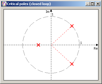
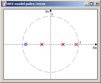
The pole map can be displayed via menu "View". This graph is usefull to check whether critical pole calculator works properly and the sampling period is correctly set. It should always look similarly to following picture:
|
In case the single real pole is critical (z = -1 + j*0) the Ziegler-Nichols tuning method is not very successfull. This usually happens when to slow sampling period is used.
The pole/zero map can be displayed via menu "View". This might be usefull for identificator stability checking. It uses cubic equation solving algorithm and I'm not totally sure it does work correctly (only few equation have been tested).
|
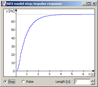
The function can be displayed via menu "View". The graph axis drawing algorithm is very nasty so I have no idea if it will work properly for bipolar waveforms but at least for unipolar it seems to be OK.
|
Double click to any graph should display image export dialog. The image is saved in 24-bit bitmap. If the REC button is pressed the file "rec.csv" in program directory is created/truncated and program logs graphs content.
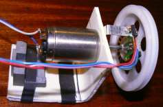
For testing purposes I've choosed small DC motor. It has no markings that can be found and probably it's not even motor. It has lot of poles, windings has no core (just impregnation) and it runs without heating up to 30V so it's probably tacho dynamo but for this purposes it's just fine. To increase dynamic a little I add some light plastic wheel. At full 12V it runs at some 3000rpm (60Hz). For a feedback I'm using some reflex type opto sensor from old video with 24 pulses per rev.

|
Dominant time constant is about 800ms so I've choosed sampling period to minimum 70ms. Sampling rate is also maximum for my
sound card (96kHz).
For easier identification I used auto step generator with period 8 seconds and 25Hz peak-peak steps (1500rpm). The model
started to work properly after some 7 seconds and at this point I enabled adaptive tuning mode. After some 10 more seconds critical
parameters stabilized.
Ziegler-Nichols method is set to version with suppressed overshoot.
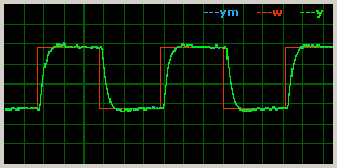
After some fine tunning of anti-windup time constant Tt, derivative component filter N and beta
I got this pretty response to control step:
|
|
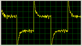
The PWM signal is quite noisy but this is caused by noise in feedback. Currently I'm using the basic method for waveform processing -
counting pulses and their total length.
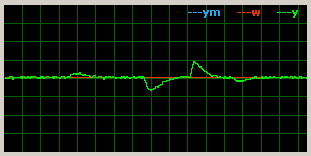
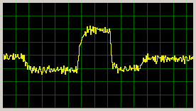
Response to error steps at input of the process (multiplicative - supply voltage changes 12-16-7-16-12V):
|
|
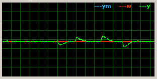
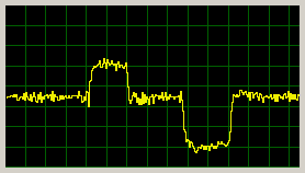
Response to error steps at input of the process (additive - adding some currents to motor):
|
|
Conclusion: sound card can be clearly used as input/output interface for discrete regulator but it is limited by inserted delay and time resolution. The concept I used doesn't allows transfer delay lower than some 80ms.
| Last update: 10.10.2012 |  |
 |