
All previous experiments
with TFT patterns generators were just TFT communication tests. The main goal was to make
controller with video-RAM.
Because I was too lazy to wire full parallel bus to the MCU I've decided to use serial port
for my first experiment.
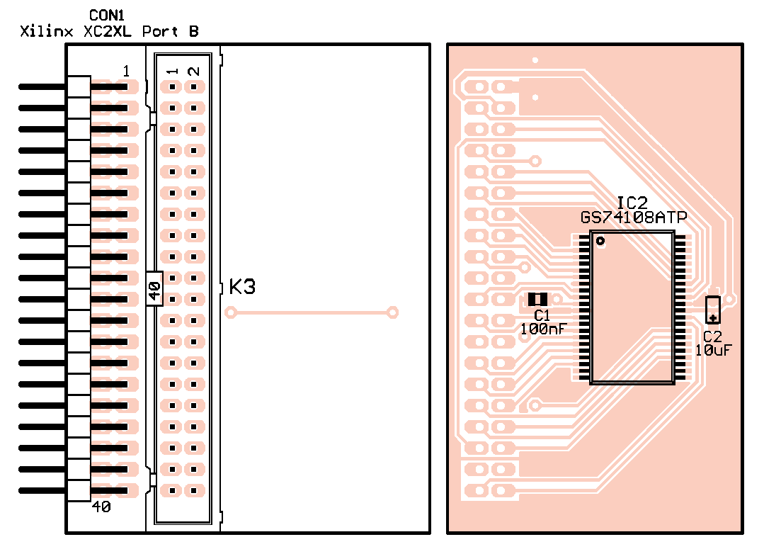
Same as for previous experiments I've used Digilent kit XC2-XL with Xilinx CoolRunner 2
CPLD (XC2C256-7).

|

|
640x480x18-bit TFT module is connected to the CPLD with 100R damping resistors to reduce high slew rate. Optimal resistance depends on cable type and its length. In my case the cable is 10cm long, 1.27mm flat cable.

|
TFT is connected with static ENABLE signal so visible area is fixed according to datasheet.
Color data lines are connected in 16-bit mode only because the video memory is organized as 16-bit too.
Since CoolRunner I/Os are not 5V tolerant the serial input RXD is protected with series resistor
and fast diode as it is recommended in application notes.
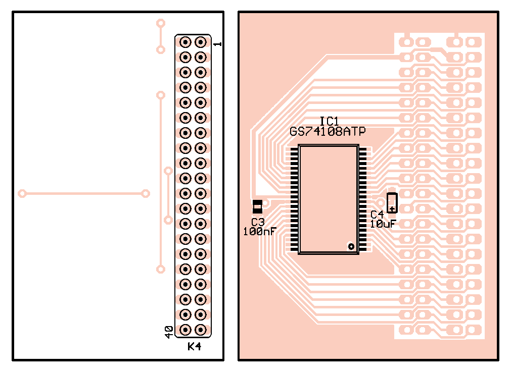
640x480 image in 16-bit color depth requires 600kiB frame memory so I'm using two 8-bit 512kB SRAM chips connected as one 512k x 16-bit SRAM. Speed grade is 10ns, it's not so expensive and the timing is much easier. Memory is connected to port B of the kit where is only one special function I/O (GSR).

|
Since the PCB routes are short enough it works without pullup or damping resistors this time.
PCB drawings:
assembly top,
assembly bottom,
PCB top,
PCB bottom.
There are two possible ways how to implement controller. The simpler method requires two independent RAMs where
one is used for refresh and the second one can be freely accessed by MCU without need for WAIT signal.
Once the drawing is done both memories can be switched (double buffering). This solution is easy to program but
it requires large PLD with lot of I/Os and those are quite expensive.
Another way is to use single RAM in time multiplex where one half of cycle is used for TFT refresh and
second half for new data storage. This method is more cost effective but it is quite complicated to set memory timing.
Also write speed is limited by pixel clock rate. In case of 640x480 TFT it's some 25MB/s for 16-bit bus (with no WAIT signal).
At first I was thinking of the first variant but fortunately I was able to set the timing correctly so I'm
using multiplex variant.

|
Theoretical SRAM and TFT timing:

|
I have no idea how it looks like in real but it seems it works with no errors. It's quite surprise to
me because I'm using very inaccurate timing that definitely doesn't meet datasheet requirements. For final version
I'll rather use at least 75MHz master clock which should be enough to set timing correctly.
As I mentioned earlier the image data are send via USB-serial line. Defaultly it's set to 3Mbit/s (FT232 maximum)
but it should work up to 12Mbit/s with 48MHz master clock. When two bytes are received (one pixel) RXC flag is set for
one cycle and new pixel is stored into SRAM with address post-incrementation. I've also implemented receive timeout
so if no pixel is sent for more than some 500ms the write address is cleared and it's possible to write new image.
Following zip file contains also two utilities. One is for 24-bit BMP to 5-6-5 RAW conversion (format
required by controller), second one is simple console terminal that sends files to selected COM port at specified rate.
WebPack 9.1i project to download: CoolRunner2_TFT_serial.zip (1524kB).
Some pictures displayed on Sharp's LQ064V3DG01 TFT:

|

|

|

|
And short video:
| Last update: 5.6.2012 |  |
 |