 |
For a past few years I'm involved in the development of digital sampling setups for primary and secondary metrology of electric quantities. In past 10 or maybe 15 years an intense research is running in order to digitize and automate so far analogue measurement setups. For instance recently a plenty of algorithms for harmonic analysis of the waveforms were presented. These enabled design of very accurate setups for measurement of power, phase shift, THD, impedance and many other specialized parameters with measurement uncertainty comparable to the traditional analogue systems. The setups are based on the high-end digitizers (ADCs). For the lower sampling rates and highest accuracy/stability the unique sampling multimeter HP/Agilent/Keysight/WhateverItWillBeCalledNextYear 3458A is often used. It is some 30 years old design but it has no alternative which is funny because due to idiotic RoHS policy it won't be sold anymore in EU a soon in the rest of the world. And no replacement is planned. Hopefully China will solve the problem if you know what I mean. :-) This DMM is a real masterpiece capable of digitizing up to 100 kSa/s with noise floor -120 dBfs. On the other hand with slower sampling it can be used as an 8.5-digit DMM. For higher bandwidths some of the professional digitizers are used such as the National Instruments 5922 that can digitize up to 500 kSa/s in 24bit resolution or 15 MSa/s in 16bit resolution. However these digitizers are completely out of reach for individuals, most of the commercial sector and often even for universities due to its price (usually over 8000 Euro). There are of course cheaper variants but still it is way over 1000 Euro. Recently I was thinking of development of a digital sampling impedance bridge for high impedances and I was looking for some cheaper solution. It is of course possible to simply buy some ADC/DAC chips, few operational amplifiers and FPGA and build my own but it takes awful lot of time ot make it properly and I want to spend my time on the measurement system itself rather then on reinventing the wheel. So I decided to test an ordinary soundcard which is very common solution for many low bandwidth signal processing applications for some 20 years.
Choice of the digitizer turned out to be quite simple. I required USB type so it can be easily galvanically isolated from the PC. It should be 24bit and most importantly it must support so called 'asynchronous mode'. In this mode the soundcard generates its sampling clock by itself and PC only keeps its FIFO buffer full. This is the only way to ensure synchronous sampling of the ADC and DAC which makes any signal processing incomparably simpler. The other modes of operation with adaptive sampling rates are basically useless for means of signal processing and I don't even understand why it exist. I don't see any advantage in it except it maybe obeys some patents. After some googling I found that almost only reasonable model for reasonable price is well documented and reviewed Creative X-FI HD USB. It has good PCB layout with clearly visible analogue nad digital ground isolation, it uses ADC/DAC chips with available datasheets and it even has a ground terminal which is kind of a sign that the engineer who designed that knew something about fundamentals of the analogue design. And because this model is not trademarked as an audiophile product it even uses reasonably small rectangular case and not some hypermodern overdesigned nonsense.
When I finally had my soundcard I started some tests. I recycled my ancient code and tried goog old in/out (I mean waveIn/waveOut of course, what else, right?).
But by simply listening to the sound of a pure sine wave it was evident something is not quite right. Every time after the playback started the pitch and volume changed several times before it settled.
After some googling I found that with Windoze Vista M$ finally decided to dump the ancient sound interface and replace it with something more 21st century-ish.
Thumbs up for that because for example the way how old system mixes multiple streams with different formats was terrible. But unfortunately some brainiac screwed up the wrapper functions that provides backward compatibility for the older applications using the waveIn/waveOut.
It does something but due to the random jumps in the pitch/level it cannot be used for any serious signal processing.
There is plenty of rant about it on the internet and also lot of sure solutions but none of the proposed solutions worked for me.
So I decided to leave the 20+ years old waveIn/waveOut APIs and look for something better. In case someone is interested into details on the new Windoze audio stack it is described here:
https://channel9.msdn.com/Shows/Going+Deep/Vista-Audio-Stack-and-API
I definitely did not want to use directly the new WASAPI because it seemed to me kind of underdocumented.
So I decided to test the next oldest and simplest thing, the DirectSound interface.
At first I was a little bit skeptical if I can make it work in a reasonable time because the documentation seemed a bit ... lets say simple.
But in fact it turned out to be much simpler than waveIn/waveOut interface. There is no need for preparing/unpreparing/circulating multiple buffers.
DirectSound has simply just one circular buffer with a read (playback) or write (capturing) pointer and user just periodically fills or empties the buffers to prevent under/overflow. That's it. No more mystery.
The only nasty thing was existence of the two pointers for the capture buffer returned by the GetCurrentPosition() method because the description of what they are was of course at completely different place in the MSDN.
In case someone is interested the 'pdwCapturePosition' is the wrong one, i.e. that is the position where the newly captured data are being/will be written by the system while the 'pdwReadPosition' is the one that says from where it is safe to read the valid data. But that is really it, no more complications.
After some basic tests with line-out to line-in loopback and spectrum analysis it seems the DirectSound APIs are not screwed up as the waveIn/waveOut. The signal is stable in both frequency and amplitude. Also no spectral leakage is present in the loopback tests so evidently the ADC and DAC of my soundcard are clocked synchronously. Some of the measurements are shown in the following figures.
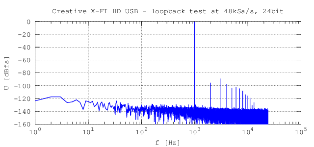 Fig. 3.1 - Line-out to line-in loopback test at maximum amplitude, 1 kHz, 48 kSa/s, 24bit, 48 kpt FFT. THD+N = 0.0047 %.
|
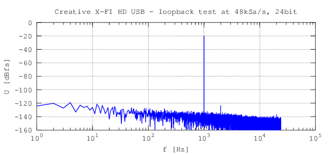 Fig. 3.2 - Line-out to line-in loopback test at amplitude -20 dB, 1 kHz, 48 kSa/s, 24bit, 48 kpt FFT. THD+N = 0.0082 %.
|
So after verifying the DS APIs are usable I started to think about development of some simple library of functions to use it effectively. My requirements were quite simple:
- To support single shot or looped playback at output device.
- To allow simultaneous capturing from capture device even several times during the output playback.
- To provide timestamps along with the captured data.
- To make it usable in LabVIEW.
The first to requirements are quite simple and obvious and there are already existing libraries for that. However the timestamp functionality is probably unknown to most of the developers. This is very useful feature for example when several waveforms are captured using a time multiplexing mode. The problem is illustrated on the multiplexing phase shift meter in the figure 4.1.
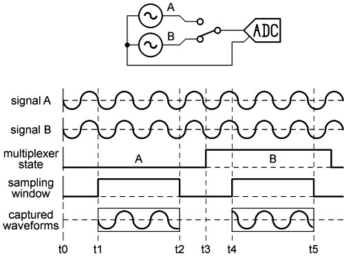 Fig. 4.1 - Time stamp problem illustration - time multiplexing phase shift meter.
|
Two signals A and B are generated and sequentially digitized by the ADC. It is clear that both signals have the same phase however the captured waveforms have obviously different phases. The apparent phase shift will be different when the measurement is repeated due to the random interval between t2 and t4 which is affected by the operating system scheduler timer granularity and various API delays. It is obvious that for calculation of the phase shift between the captured A and B signals it is necessary to know the time elapsed between the t1 and t4. Using a system timer for this won't help due to its low resolution and it is not even related to the timebase of the ADC. So one of the solutions is to simply digitize continuously from t1 to t5 and than cut out two windows from the digitized noodle as it is shown in the figure. Since we know sample count between t1 and t4 and also the sampling period TS it is easy to calculate the time shift and thus to correct the measured phase difference:

where fx is frequency of the measured signal and ΦA and ΦB are the calculated phases from the windows A and B for instance by means of DFT.
But this solution is not very practical especially for more complex multiplexing patterns.
That is one of reasons why every decent digitizer provides timestamp information along with the captured waveform.
It is a relative time between the first sample of the captured waveform and some common event, eg. reset of the device.
The timestamp is derived from the same clock as the ADC sampling itself so in terms of the digitized waveform it has absolute accuracy ... well except the jitter.
Emulating this function with the DirectSound is very simple. I simply start the capturing immediately when the device is opened even if the waveform data are not needed.
A high priority thread periodically reads the captured data and dumps it until user wants to start capturing. In that case the thread starts filling the user capture buffer.
Once it's filled it starts dumping the data again. But even if it dumps the samples it counts them so in every moment the thread knows number of the samples from its start so it can return the relative timestamp.
The last requirement, i.e. the support for LabVIEW is a bit more complicated. I'm not a big fan of the LabVIEW "programming" but the environment was available at my workplace and some programs were already made in it so I started to using it.
It is quite effective if I need quickly some simple measurement loop. After some time I learned how to use it effectively.
That is in most cases just to control the instruments and for the user interface which is quite simple and fast.
The most important part, i.e. the data processing for the sampling systems is made in the environment dedicated to data processing and calculations, which is in my case GNU Octave.
This way the whole processing is transparent and can be easily modified and of course analyzed using simulated data.
For the effective communication between the LabVIEW and Octave me and my colleague have developed a pipe interface GOLPI [1] that makes it really simple.
So now I have several quite complex programs that uses professional digitizers but all of them are made using generalized instruments so they can operate with any other HW.
That is why I need support in LabVIEW because than I simply include the DS drivers and it should work with no other modifications.
But whoever programmed in the LV knows that calling complex library functions is a pain.
Calling some WINAPIs with its crazyass structure parameter such as WAVEFORMTEX id merely impossible and even National Instruments recommends to use a DLL wrapper. So I did it. It is optimized so it requires nothing else but standard data types so the calling is quite simple.
| [1] | Mašláň S., Šíra M. GOLPI - Gnu Octave to Labview Pipes Interface. November 2014. https://decibel.ni.com/content/docs/DOC-35221, http://kaero.wz.cz/golpi.html |
The whole DSDLL library is made as a DLL. It contains the necessary functions for enumeration, playback, capturing, configuration and status checking. All of the functions are made so they contain only basic data types such as int32, uint32, double and pointers so it can be easily called from LabVIEW.
But of course it can be used in any other environment. After years of using Borland BDS2006 Turbo C++ I found that it cannot be easily installed in Windoze 7 (requires some prehistoric .NET).
I was too lazy to solve this in virtual machine so I developed the whole library, demos and utilities in the M$ Visual Studio 2013. Unlike the new RAD Studio (successor of Borland) it's free and it seems to work quite well.
Full source code and binaries download (version 1.0, 2016-08-20): dsdll_20160820.zip.
Since it is basically nothing special I decided to make it open under a GNU Lesser General Public License which is a little bit less restrictive than common GNU GPL. So the DLL can be linked even to commercial solutions. The demos and utilities are distributed under even less restrictive license WTFPL. Yeah I know, it's a kind of a joke but I like the idea.
The description of the particular functions is in the source code so I won't go into details here. I'll just give a few examples of usage in C/C++.
Following code is a simple example how to enumerate the devices. First the lists of input and output devices are filled by calling sb_enum(). Than one of the devices is selected by its ID where 0 is the default device. The function sb_enum_get_device() is used to get the device GUID from the lists. After that the lists should be cleared by calling sb_enum_clear_list(). The GUIDs are then used to finally open the devices by sb_open().
  // initialize empty lists of input/output devices
  TSDev dsolist = {0,0,NULL};
  TSDev dsilist = {0,0,NULL};

  // fill the lists with DirectSound devices
  sb_enum(&dsolist,&dsilist,NULL,NULL);

  // obtain the GUID of selected input/output devices, id = 0 is default device
  GUID outguid;
  GUID inpguid;
  sb_enum_get_device(&dsolist,output_device_id,&outguid,NULL,0);
  sb_enum_get_device(&dsilist,output_device_id,&inpguid,NULL,0);

  // clear the lists
  sb_enum_clear_list(&dsolist);
  sb_enum_clear_list(&dsilist);

  // now the DirectSound can be initialized by calling sb_open() with the GUIDs
  sb_open(..., &inpguid, &outguid, ...);
Following code shows how to open both input and output devices. First the format is specified. The sampling rate is common for input and output.
The channel counts may differ but must be valid even if input/output is not used! The sb_open() function can take NULL in place of the GUID.
In that case the input/output device is not opened. Empty (zeroed) GUID opens default device. This is not standard behavior of DirectSound, it was added by me in the DSDLL. In case of the default devices the enumeration is not necessary.
When the input device GUID is assigned the sb_open() immediately starts capturing from the device! The wave data are dumped untill user requires capturing but the capture thread runs continuously untill calling sb_close().
  // create a wave format descriptor
  TSBfmt fmt = {sampling_rate,output_channels,input_channels,wave_format_id};

  // make&clean DirectSound structure
  TSBhndl ds;
  ZeroMemory((void*)&ds,sizeof(TSBhndl));

  // create DirectSound object (both input/output devices)
  sb_open(&ds,&inpguid,&outguid,&fmt);
Once the sound interface is not needed anymore it can be terminated by calling the sb_close(). It will terminate playback and capturing if it's still running.
  // close DirectSound devices
  sb_close(&ds);
If the output device was opened the playback of the given waveform data can be initialized by calling sb_output_write(). The 'data' is array of the samples in the format specified by 'TSBfmt' structure used for opening. The data are organized as interleaved channels, little endian. The playback can be started immediately by sb_output_write() or later by calling sb_output_play(). The sb_output_play() can be called repeatedly. All functions are nonblocking so it returns immediately.
  // writing data and starting playback immediately (loop_mode > 1)
  sb_output_write(&ds,(void*)data,samples_count,loop_mode);


  // writing data but not starting playback yet
  sb_output_write(&ds,(void*)data,samples_count,0);

  // doing some stuff ... for instance setting the volume and panning
  sb_output_set_volume(&ds,0,0);

  // starting the playback (only if the data were written before)
  sb_output_play(&ds,loop_mode);
The playback can be stopped at any time by calling sb_output_stop(). The state of the playback, i.e. the position of the playback read pointer and few other information can be obtained asynchronously by calling sb_output_status(). Example of waiting for playback end is shown in following code.
  while(1){
    // get playback status
    DWORD count;
    int stat;
    int err = sb_output_status(&ds,&stat,NULL,&count,NULL,NULL);

    // leave if playback is done or no output data or something f.cked up
    if(err || !count || !stat)
      break;
    else
      Sleep(50);
  }
If the capture device was opened the capturing may be initiated by calling the sb_capture_wave(). This function is synchronous so it returnes when the capture is completed. Example for 'float' wave format (DSDLLF_IEEE32) is shown in the following code.
  // allocate buffer for the captured data
  float *buf = (float*)malloc(sample_count*input_channels*sizeof(float));

  // capture the waveform, return actual samples count 'read' and the 'time_stamp'
  double time_stamp;
  DWORD read;
  sb_capture_wave(&ds,(void*)buf,sample_count,&read,&time_stamp);
Alternatively the required byte size of the capture buffer can be obtained by calling sb_capture_get_size(). Although the function sb_capture_wave() is synchronous (blocking) there is a way to check state of the capturing and to terminate it by calling sb_capture_wave_get_status() and sb_capture_wave_abort() from a different thread. It is a bit unusual solution but in my case these function are useful only in GUI of the application which runs in different thread anyway.
There are several additional functions used for configuration, error handling and so. The functions are described in the source code and header file. One of the useful features is debugging. If the file named 'dsdll.ini' is present in the folder with the 'dsdll.dll' and contains following:
  [DEBUG]
  ;enable logging (0-none, 1-basic function, 2-include status checking functions)
  log = 1
then the log file 'debug.log' will be created in the same folder. It will contain some information maybe useful for debugging if something goes wrong.
The INI file can also contain following records:
  [CAPTURE]
  ;default capture thread priority (see SetThreadPriority() API for values, default: +1 - above normal)
  thread_priority = +1
  ;default capture thread idle time [ms] (typically 10 ms, max 500 ms)
  thread_idle_time = 10
which alters the capture thread timing. The priority increasing may be useful when the CPU is heavily loaded or on single core machines. The capture thread idle time is the Sleep() period when no capturing is in progress. Increasing the value decreases usage of the CPU but it cannot be increased over some 500 ms because the capture buffer has only about 1 s in length.
I've made a few examples of the usage in C/C++. the demos are part of the source code download above.
This simple demo does nothing more but enumerates the devices, opens output device and starts playback of ramped sine wave. It uses default output device.
Binary download (version 1.0, 2016-08-20): dsdll_demo_basic.zip.
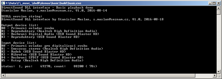 Fig. 4.2 - Basic playback demo.
|
This simple demo enumerates devices, opens both capture and output device, records few seconds of input waveform and then plays it in a loop using output device. It uses default capture and output devices.
Binary download (version 1.0, 2016-08-20): dsdll_demo_basic.zip.
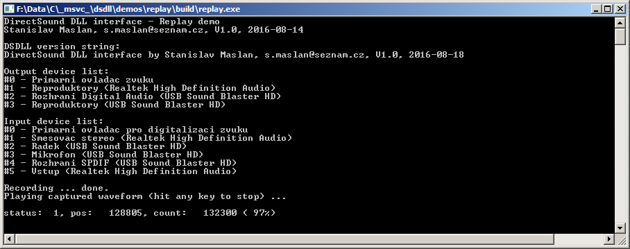 Fig. 4.3 - Basic replay demo.
|
This demo demonstrates basic usage of the timestamps for measurement of a phase stability. The soundcard line-out is connected to line-in (loopback). The output devices generates continuous sine wave which is generated so it is coherent with the loop length (integer number of samples per sinewave period). The capture device starts capturing from the input device repeatedly with pseudorandom delays. The number of the captured samples is again set so the captured window is coherent with the signal. Then DFT is used to calculate amplitude and phase of the captured waveform. Timestamp is used to fix the random phase jumps due to the random triggering as was described here. The phase Φx returned by the DFT is corrected by following formula:

where the fX is frequency of the signal in [Hz] and tS the timestamp in [s]. If everything works as it should the corrected phase Φ' should remain constant no matter when the capturing was triggered even for several days.
It should show only slow drifts due to the temperature instability of the soundcard components and of course some noise.
Fast drifts or sudden jumps in the phase indicates the sampling is not synchronous (soundcard with adaptive sampling rate mode) or eventually buffer overflow/underflows due to slow CPU or wrong setup of the DSDLL timing.
Binary download (version 1.0, 2016-08-20): dsdll_demo_timestamp.zip.
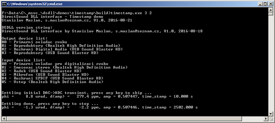 Fig. 4.4 - Timestamp phase stability demo.
|
Following graphs shows example of the measurement with this utility with my Creative X-FI HD USB. After some 80 minutes of measurement the maximum deviation of the phase was some 1.5 µrad and amplitude below 4 ppm which is not bad for a 70 Euro 'digitizer'. In lab with stable temperature it may be even better.
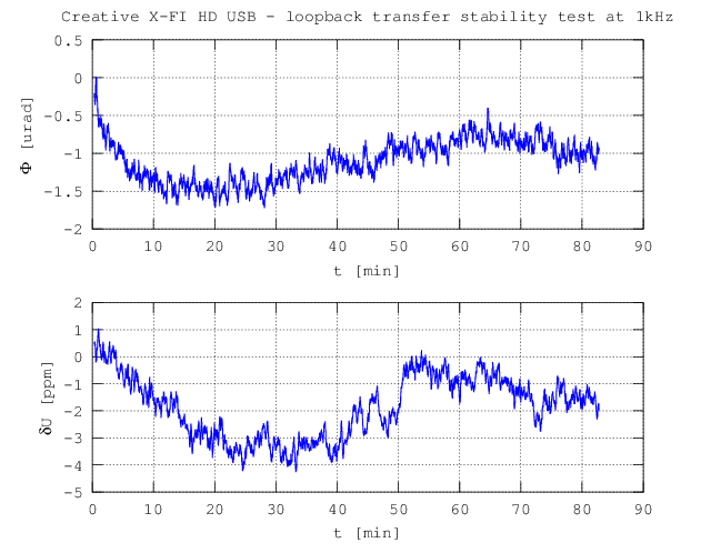 Fig. 4.5 - Line-out to line-in loopback transfer stability, amplitude 0.5, 1 kHz, 48 kSa/s, 24bit.
|
I often use GNU Octave for complex processing of the data from the sampling systems because it's incomparably simpler than C/C++.
But it is not trivial to use DLL functions directly in the Octave so I've made a simple executable utility 'dsrec.exe' that can be called from any environment including the GNU Octave.
It is a simple console application that can enumerate the devices to the stdout or to a file.
Then it can start generation of the given waveform at the selected DirectSound output device either in a loop or in single shot mode. Simultaneously with that it digitizes the signals from capture input.
The output and captured waveforms are transferred via files.
So it can be used for a simple measurements where whole measurement can be made using a single waveform capture. Details of the usage are hopefully obvious from the console printscreen. Source code is available above.
Binary download (version 1.0, 2016-08-20): dsdll_dsrec.zip.
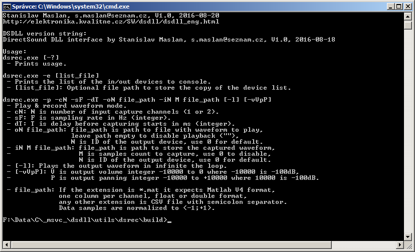 Fig. 4.6 - DSDLL utility for simple measurements.
|
This simple demo uses the soundcard as a synchronous phase shift meter.
It generates two sinewaves with a given phase shift at the selected DirectSound device outputs and digitizes the signals using selected DirectSound capture device inputs. It calculates the phase of the signals using ordinary FFT so it cannot handle externally generated signals because those are of course not coherent with the sampling window!
But the generated signals can be connected via analyzed passive/active circuits so in this case it can be used as a phase shift meter. More details are shown in the script itself.
It contains no corrections to the interchannel phase errors or crosstalk so the accuracy is very limited but it can be easily implemented.
It requires only basic packages so there should be no trouble running it. It was tested in Octave 3.6.4/4.0.0 but with some minor syntax modifications it should run in Matlab as well.
Example of the measurement is shown in the following figures. The phase error is just 0.0025° which is not bad without corrections. The stability is also acceptable.
Download (version 1.0, 2016-08-20): dsdll_octave_synphase.zip.
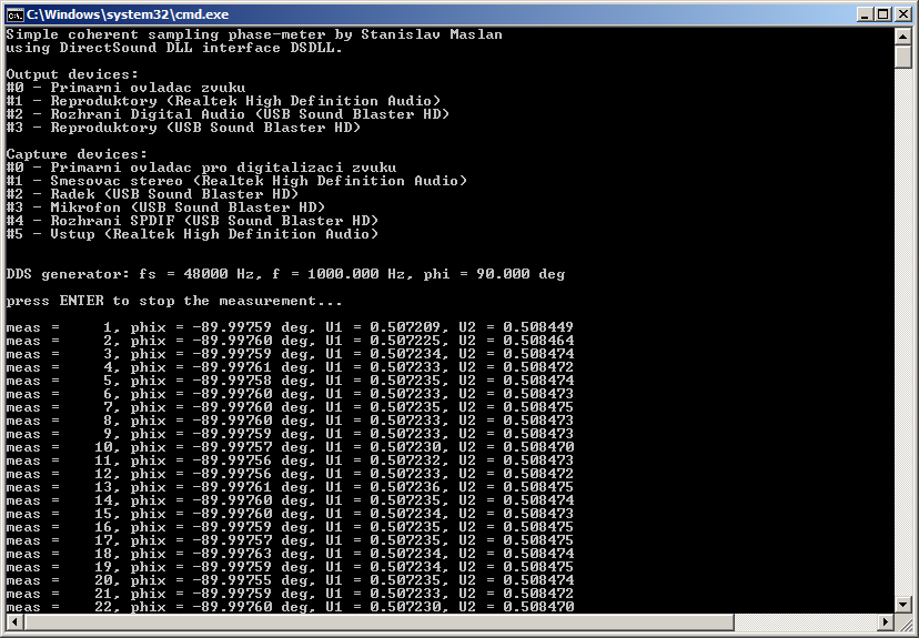 Fig. 4.7 - Example of measurement of the phase shift using 'dsrec.exe' utility and GNU Octave. f = 1 kHz.
|
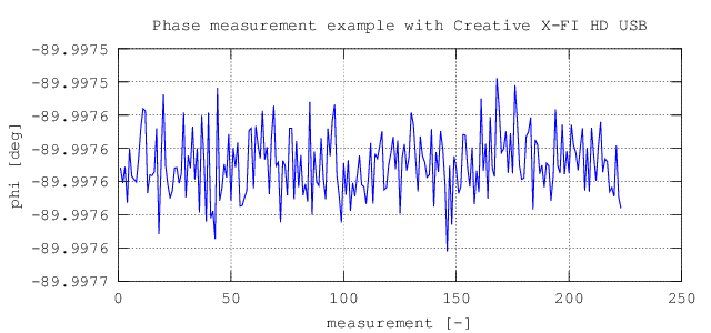 Fig. 4.8 - Example of measurement of the phase shift using 'dsrec.exe' utility and GNU Octave. f = 1 kHz.
|
This simple demo measures the input impedance of the soundcard channel using a reference resistor with known impedance. Output of the soundcard generates sinewave at selected frequencies. One input channel of the soundcard is connected directly to the output to obtain reference voltage U1. The second input channel is connected via reference impedance Zref to obtain voltage U2. The Zref together with the input impedance Zi forms a voltage divider so the input impedance can be easily calculated as:

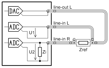 Fig. 4.9 - Soundcard connection for measurement of input impedance.
|
To make it a little more accurate I also implemented interchannel gain/phase correction which
is performed with both inputs connected together to the output channel. A correction file is
created and it is used to fix the gain/phase errors of the soundcard.
The reference resistor must be chosen so it has impedance close to the input impedance. In my
case it was 10 kΩ resistance standard. If RLC meter is not available the parallel capacitance of the resistor must be guessed.
For 0207 resistors it is usually some 0.3 pF but this is negligible error due to the
fact the input admittance of the input channel in connected in parallel to the unknown capacitance
of the cable. The admittance of the cable can be found by connecting another identical cable in
parallel to the analyzed input and repeating the measurement. Difference between the measured CP
should be capacitance of the cable and it should be independent to the frequency.
The script requires only basic packages so there should be no trouble running it. It was tested in Octave 3.6.4/4.0.0 but with some minor syntax modifications it should run in Matlab as well.
Example of the measurement is shown in the following figures. The input resistance is almost independent to the frequency. The capacitance dependence looks a little bit suspiciously but I measured the same thing using a regular RLC bridge so it is probably correct.
Download (version 1.0, 2016-08-20): dsdll_octave_inpz.zip.
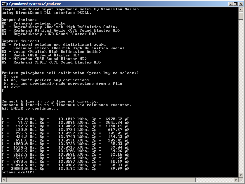 Fig. 4.10 - Example of measurement of the input impedance of Creative X-FI HD USB using 'dsrec.exe' utility and GNU Octave.
|
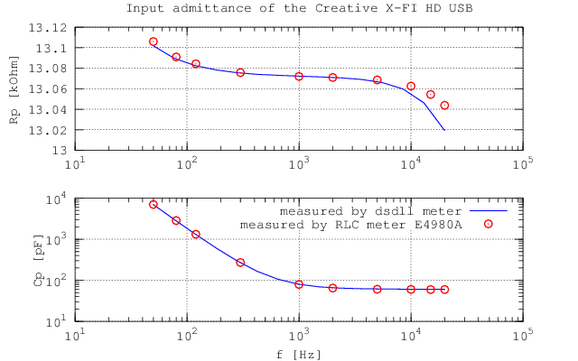 Fig. 4.11 - Example of measurement of the input impedance of Creative X-FI HD USB using 'dsrec.exe' utility and GNU Octave.
|
Update 2.9.2016: I already tried to use Creative X-FI HD USB as an ADC and DAC in several applications. Since I often measure with uncertainties in order of ppm (0.0001 %) and µrad, is it essential to eliminate or apply corrections to various interferences and errors. One of the most common sources of the errors is crosstalk between the input channels and also output to input crosstalk. Measuring these may seem like a simple task but it is more complex then it looks like. The problem of the crosstalks is shown in the following figure.
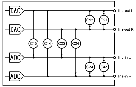 Fig. 4.12 - Problem of the crosstalks in soundcard.
|
It is clear there are at least eight crosstalks inside the soundcard. Four if only one output channel is used which is my case. To enable corrections it is necessary to measure all particular crosstalks separately and they must be measured as a complex numbers, i.e. both amplitude and phase. The amplitude measurement is trivial. Phase is a bit more complicated. For instance for measurement of C34 it is not possible to simply generate sine at 'line-out R', connect it to 'line-in L' and measure parasitic voltage U1R at 'line-in R' because the voltage is superimposed with voltage induced via coupling C24. Only way to measure C34 seems to be to use another source of the signal which is a problem because it won't be coherent and it makes data processing complicated. Another way is to measure U0R voltage at 'line-in R' induced via coupling C24 when the 'line-in L' is unconnected from the 'line-out R' and then subtract it when the C34 itself is measured. However that has a small problem. And it's a big one. When the voltage U0R is measured there can't be a reference voltage at any input because of the crosstalks so the phase of the U0R cannot be determined. Only amplitude. But without the phase this technique is not possible. So obviously only suitable solution is to split the measurement into two steps using a time multiplexing mode and a multiplexer that can disconnect the analyzed line-in from the line-out in the middle of the measurement. For this purpose I've made a simple circuit that is shown in the following circuit diagram.
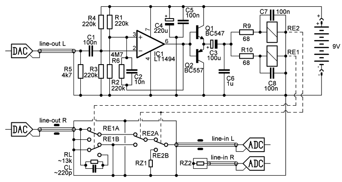 Fig. 4.13 - Multiplexer for measurement of soundcard crosstalk.
|
To make this measurement useful the multiplexer must ensure isolation at least some -140 dB.
For the purpose I used two relays connected in series. The distance between them is some 2 cm and I had to shield the second relay by a metal casing to prevent capacitive coupling via plastic cases of the relays.
The relay coils are grounded to the signal ground, blocked by a ceramics and isolated by RCR network to decrease coupling via the coils.
The RE1 is also connected so when the path through the multiplexer is isolated the line-out is loaded with substitution impedance RL and CL which is set to approximately equal value as line-in admittance including the cable. This ensures almost constant loading of the line-out independent to the state of the multiplexer.
The measured isolation of this solution is better than -150 dB at 20 kHz which should be enough for the purpose.
The relays are ordinary latching ZETTLER AZ850P1-5 which turned out to be quite good for the price.
I definitely didn't want to control it via COM port or USB so I decided to use the unused output of the soundcard to control the relays.
It generates short positive and negative pulses. These are latched by the schmitt trigger with J-FET input opamp with rail-to-rail output.
The output is amplified by complementary transistors and C3 generates the latching pulses for the relays.
The resistors are set so with the 1 ms pulses it safely switches even at half output amplitude of the line-out Creative X-FI HD USB.
Idle current is some 40 µA. It can be tunned to few µA but I had not the right resistors. :-)
But in another multiplexer I reached some 0.5µA idle current so with the 9V lithium battery it can go for years and it's not even beneficial to turn it of. That is a big advantage of the latching relays.
So the measurement process is divided into two steps: In the first step the multiplexer is enabled, so the 'line-out R' is connected to 'line-in L'. Voltage vectors U1L and U1R at both line-in channels are measured.
In the next step the multiplexer isolates the path and the analyzed line-in is terminated with impedance RZ1 which should be similar to the impedance of whatever will be connected to the input for the real measurement.
In my case it is 1 Ω resistor, which is roughly output impedance of opamp with some cable.
In this state the voltage vectors U0L and U0R at both channels are measured again.
Channel 'line-in R' is loaded by the impedance RZ2 = RZ1 in both steps.
Vectors U1X and U0X are synchronized using the timestamps. Next the crosstalk coefficients can be calculated:
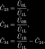
To measure the C43 the line-in channels must be swapped. Similarly the line-outs must be swapped to measure the coupling from the second line-out channel if it's needed.
The measurement procedure itself is made in Octave, because I don't need any GUI for it. Scripts were tested in Octave 3.6.4 and 4.0.0 but with some minor syntax changes it should work in Matlab as well. Usage is described in the script itself.
Download (version 1.0, 2016-08-31): dsdll_octave_crosstalk.zip.
Following two graphs show measured dependencies. It seems the measurement with reference signal at both line-ins show the same values. It is quite interesting the output to input crosstalk has optimum around 1 kHz and it grows to both sides. The crosstalk between the input channels is almost constant -94 dB up to some 3 kHz but then it grows significantly, possibly due to capacitive coupling. It is obvious that using the soundcard for any serious measurement using both channels at once is not possible without corrections. It also explains the errors in the experimental phase shift meter because honestly I expected much better results.
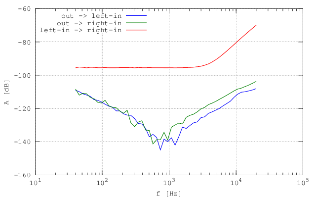 Fig. 4.14 - Line-in/line-out crosstalks for soundcard Creative X-FI HD USB with output load 13 kΩ. Reference channel line-in L. |
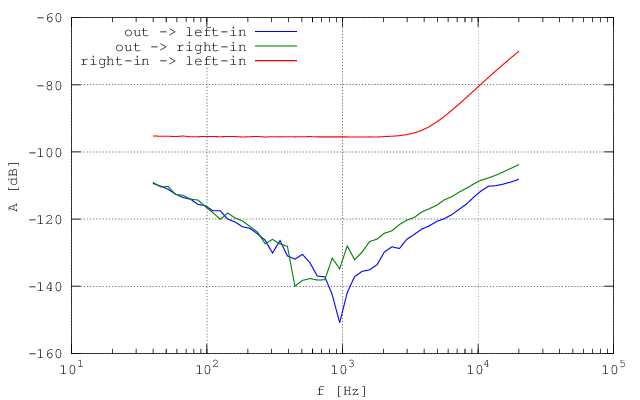 Fig. 4.15 - Line-in/line-out crosstalks for soundcard Creative X-FI HD USB with output load 13 kΩ. Reference channel line-in R.
|
Since the shape of the output-input crosstalk is a bit funky I repeated the measurement with different loading of the line-out. I simply connected resistors 1 kΩ and 100 Ω to the input of the multiplexer. Following graphs show the change in the dependencies.
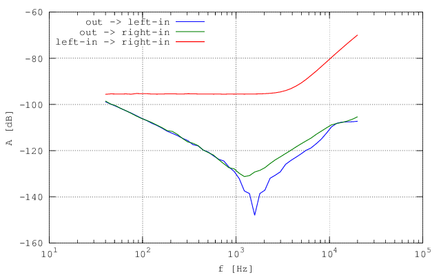 Fig. 4.16 - Line-in/line-out crosstalks for soundcard Creative X-FI HD USB with output load 1 kΩ. Reference channel line-in L. |
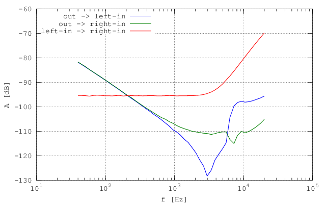 Fig. 4.17 - Line-in/line-out crosstalks for soundcard Creative X-FI HD USB with output load 100 Ω. Reference channel line-in L.
|
Crosstalk at low frequencies has increased significantly and at high frequencies it has even funkier shape. I'm not in the mood the make reverse engineering of the soundcard HW to find out cause of the problem but the conclusion is it should not be loaded at all. Preferably the output should be buffered by some J-FET opamp voltage follower to minimize the effect. Capacitive loading of the cable will be still there but the real component will rise to MΩ range.
Update 22.4.2017: I finally got some time to polish my LV library for the DSDLL. It is basically just a wrapper of the DLL functions made in such a way so it can be easily used as a direct replacement for any professional digitizer (I already tried it in few of my applications). The library also contains few demos which are made so they require only basic LV without any commercial packages. That is kind of limiting because there is not even FFT in basic LV package but I made my own which is enough for the purpose.
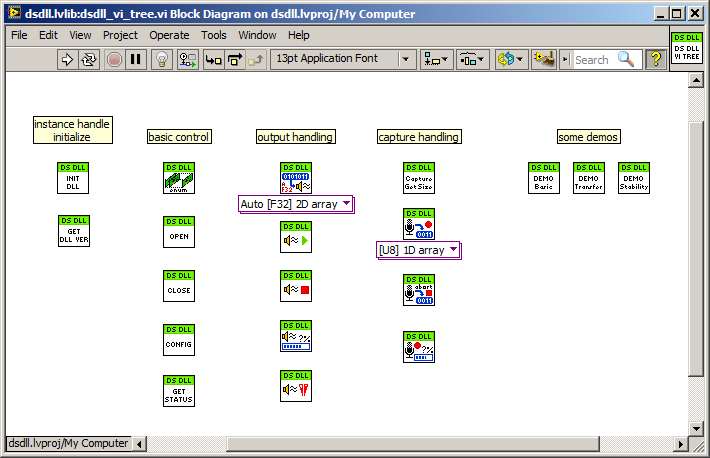 Fig. 4.18 - VI Tree of the DSDLL library for LabVIEW.
|
The library is made in LV 2013 and is distributed under GNU Lesser General Public License. It is divided to a few function groups: Initialize, Control, Output, Capture. First the DSDLL handle must be initialized. This is used to locate the DLL path. By default it is expected to have the DLL in the folder with executable. Otherwise the path must be specified. Rest of the functions are equivalent to the C/C++. Only additions in the LV library are input/output functions that works with 'double' sample format and converts it to needed audio format automatically.
Download LV source, build and demos (version 1.0, 2016-11-11): dsdll_lv2013.zip.
First demo shows basic usage of the library. It allows to record waveform from selected device and then replay it in the loop. It also asynchronously checks the buffer pointer positions.
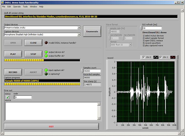 Fig. 4.19 - Basic DSDLL demo for LV.
|
This is simple demo for measurement of frequency response of a two port system using white noise as a source. It simply generates noise at one line-out and records the noise at the two line-in channels uL,R(t). It then uses FFT to obtain spectra UL,R(f) of the two voltages uL,R(t). The system transfer is calculated as a complex ratio of the spectra: G(f) = UR(f)/UL(f). Then it is filtered and displayed as Bode plot and in Nyquist plane. It is very primitive algorithm so it can be a bit noisy and sensitive to the setup but it does the trick. In the screenshot Fig. 4.20 a TT-notch-filter was measured.
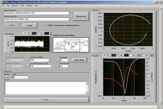 Fig. 4.20 - Frequency response DSDLL demo for LV.
|
Last demo is identical to the stability demo in C/C++. Signal is generated at line-out (both channels) and recorded at line-in. FFT is used to calculate phase and magnitude. Timestamps are used to correct the phase for the time elapsed from the first measurement. So if it does what it should it shows constant phase and magnitude with just slow fluctuations caused by the temperature instability of the analogue part of the soundcard.
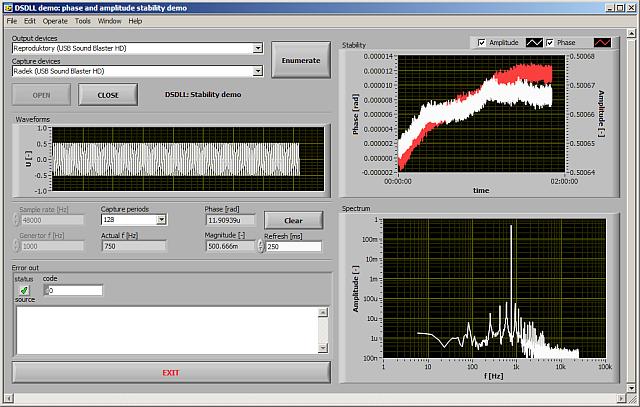 Fig. 4.21 - Stability DSDLL demo for LV.
|
Here are few specialized measurements I performed with the Creative X-FI HD USB.
I was curious how well can this soundcard measure the phase shift of two sinusoidal waveforms. Because Clarke-Hess 5000 which was used as the two phase generator runs asynchronously to the timebase of the soundcard it is not possible to measure phases of the digitized waveforms using ordinary DFT. There are several techniques how to perform harmonic analysis of noncoherently sampled waveforms. One of the simple ones is simply fitting the recorded waveform by a multiparameter model of a harmonic function. For this purpose I used function leasqr() from package 'optim' in GNU Octave. This function can be used to fit the data by basically any nonlinear function and the usage is extremely simple. Example in GNU Octave:
  % four parameter model of the harmonic function (amplitude, phase, frequency and dc offset)
  F = inline(' th(1).*sin(2*pi*th(2)*t + th(3)) + th(4) ','t','th');

  % initial guess of the captured waveform parameters
  amplitude = 0.5*(max(waveform) - min(waveform));
  offset = 0.5*(max(waveform) + min(waveform));
  phase = 0;
  frequency = must_be_known_at_least_approximately;

  % vector of initial parameters
  th = [amplitude frequency phase offset];

  % fit the 'waveform' which is function of 'time' by the function 'F'
  [..., par] = leasqr(time, waveform, F, th, ...)

  % calculate complex signal amplitude
  U = par(1)*exp(j*par(3));

  % extract the phase
  measured_phase = arg(U);
This simple calculation is performed for both the sampled waveforms and calculated phases are simply subtracted to obtain the phase shift of the signals.
It is quite simple technique and if the initial guess of the parameters is made accurate it almost always converges.
For the accuracy verifications I connected the left and right line-in channels directly to the CH5000 phase source. The measurement was repeated just for a few frequencies and the voltage was set to 1 Vrms on both channels.
And of course before the measurement itself I measured the residual interchannel phase shift by connecting the L and R channel together. This value was subtracted from all following measurements with CH5000. The result of this simple experiment is shown in table 4.1.
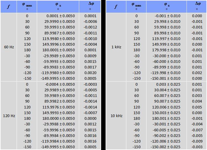 Table 4.1 - Measurement of phase by Creative X-FI HD USB using multiparameter waveform fitting algorithm in GNU Octave. The uncertainty is expanded to confidence interval 95 %.
|
Not surprisingly the results are quite good. The deviations are few m° at most in whole range. The uncertainty of the measurement is given mostly by the specifications of CH5000. The calibration data of the CH5000 are more than one year old so I can't tell if the difference is caused by this sampling phase meter or stability of the CH5000. Nevertheless the result is satisfying. It may be a little bit better if correction to the interchannel crosstalk is made but I was too lazy to make it so far.
Update 5.9.2016: I somehow could not resist to use the measured crosstalks to fix the phase shift measurement erros. I simply took the complex transfer coeficient C34 from left to right line-in and C43 from right to left line-in and used them to fix the fitted harmonic voltages:
  % U1 and U2 are the fitted complex voltages U from the fitting script

  % fix the voltages by subtracting the crosstalk voltages
  U1c = U1 - U2*C43;
  U2c = U2 - U1*C34;

  % calculate the phase difference
  phase_shift = arg(U1c/U2c);
As expected this trivial correction improved the errors especially at high frequencies where the crosstalk is the worst. The new measurement is shown in the table 4.2. Effect of the crosstalk corrections would be even bigger if the compared voltages are not the same.
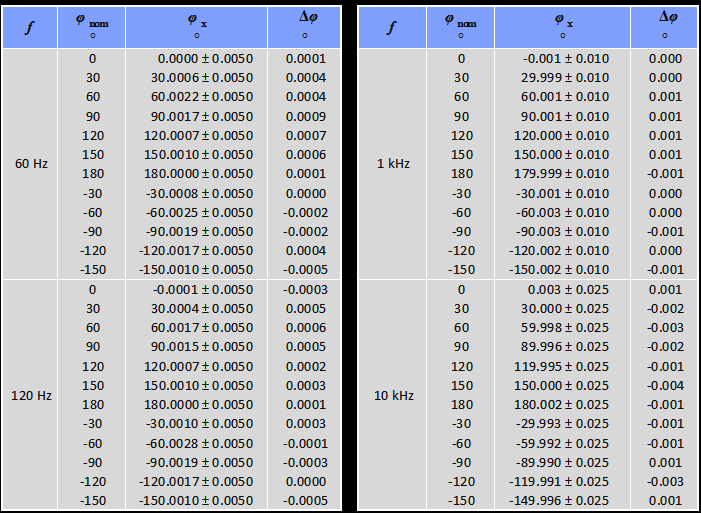 Table 4.2 - Measurement of phase by Creative X-FI HD USB using multiparameter waveform fitting algorithm in GNU Octave with crosstalk corrections. The uncertainty is expanded to confidence interval 95 %.
|
| Last update: 22.4.2017 |  |
 |